2Literature Review
- Author
- Leonardo Pinero-Perez
- Written
- 2018 · Thesis, University of Texas at Arlington
- Original
- Full thesis · 105 pages
- Contents
- Chapter 1 · 2 · 3 · 4 · 5 · Appendix A: Nomenclature · References · Acknowledgments and Biographical Information
Converted from the original PDF on with Claude Opus 5.5. The wording is unchanged, except: my name is spelled without accents, and Tables 1.1 and 1.2, pictures in the PDF, are typed out. Equations, figures and numbering follow the original. Conversion not yet checked against the PDF.
2.1Historical Spacecraft
It is important to first understand historic spacecraft designs for re-entry vehicles. From here, known design parameters can be used to validate the optimal results. This is under the assumption that the design processes used lead the programs of these successful vehicles to a near-optimal design, at least relative to a random combination of independent design parameters which would certainly fail to produce desirable results for re-entry.
2.1.1Capsule Vehicles
The first studies on re-entry were borne out of a military objective to deliver nuclear warheads in a sub-orbital flight [10]. The warheads would be propelled into space by an inter-continental ballistic missile (ICBM) and return to Earth over an enemy target at hypersonic velocity. It was discovered that the ballistic coefficient was an important property in re-entry. This was determined by these return vehicle parameters:
To increase accuracy and warhead velocity, a higher ballistic coefficient was needed. This makes sense, as increasing weight while lowering the drag coefficient and frontal area would allow a payload entering from orbit to retain its kinetic energy for longer portions of the entry path, since its path is more resistant to atmospheric disturbance. This was a good property for missiles, where shorter flight times and pin-point accuracy was needed for effective strikes. However, since the warhead would only slow down at lower portions of the atmosphere where the air was of sufficient density, the g-loading on the craft was not tolerable for human flight. Additionally, the warheads endured a large heat pulse, which was combatted by large metal heat sinks [10]. Materials which vaporize upon heating (known as ablative material) also protect the warhead from excessive temperatures upon re-entry.
For human passengers, the flight path angle is drastically reduced to limit the g-loading to tolerable levels of about 8g (assuming the crew is facing backwards with respect to the direction of flight [10]). The decreased entry angle and ballistic coefficients increased the flight time, so a thicker layer of ablative material was required.
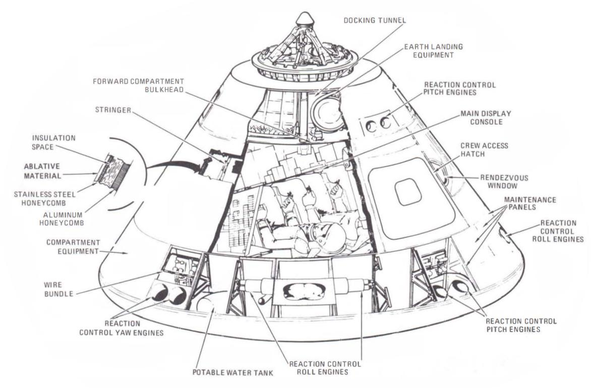
Capsule vehicles need a device to decelerate them sufficiently for touchdown, such as a parachute or deployable wing (i.e. a Rogallo wing). Once the vehicle was in the subsonic flight regime, the flight phase using the deployment of such a device became known as the “Decoupled Mode” [10]. This decoupled mode is a portion of the re-entry vehicle’s total mass, typically constituting about 8% of the dry weight [12].
The entry of a purely symmetric capsule is known as a ballistic re-entry, where the only significant aerodynamic force present opposite of and aligned with the direction of flight (aerodynamic drag), such as a bullet, arrow, or stone. Since there is negligible lifting force, the lift-to-drag ratio of a ballistic vehicle is near zero. The Mercury program was the only manned American program whose mission profiles used a purely ballistic re-entry capsule [10].
Capsules later developed a limited lifting capability (termed semi-ballistic), which could drastically reduce acceleration and thermal loading while increasing accuracy. Increased accuracy significantly reduced recovery costs. Lift modulation during descent also reduces thermal and acceleration loads on the craft [13].
2.1.2Wing-Body Vehicles
Wing-body vehicles were developed as advanced aircraft with radically increased flight envelopes [10]. The concept was first introduced by Eugen Sänger, who imagined spaceflight as a manned endeavor from rocket-powered “stratospheric” aircraft. His idea was to modify existing missile designs by attaching wings and control surfaces, where by early 1944, he was working with rocket scientists for a long-range rocket plane (winged-body vehicle) to aid in the German war effort [14]. The Silber Vogel, as it was called, was to be a bomber capable of taking off from Germany and bombing the United States. The configuration of the aircraft allowed for fuel and engines to be contained in a slender body, while wings would serve solely as aerodynamic means to control flight and the maintain lift needed for its unique flight profile.
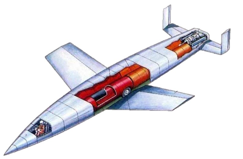
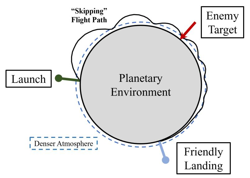
The aircraft would be launched into the upper atmosphere and edge of space, and upon falling back steeply into the denser atmosphere, initiate a pull-up maneuver and “skip” back into the less dense atmosphere. Since the rocket is maintaining its velocity from the rocket launch and flight path through the upper atmosphere, significant range can be maintained, only slowly dissipating throughout the long-range flight. The intention was for the aircraft to land at least as far as the Empire of Japan. Dynamic soaring (as this skipping is called) significantly increases the range of a suborbital flight by skipping across the surface of the atmosphere as a rock would across a water pond.
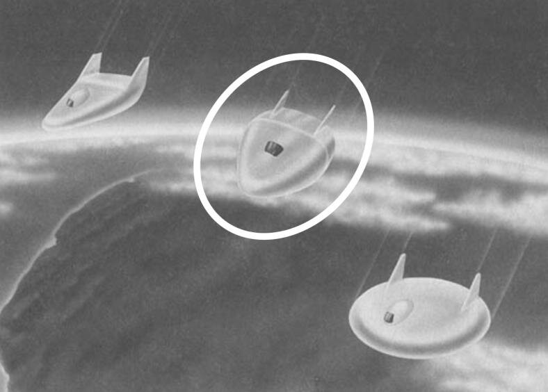
The Dyna Soar was named after this flight profile, although it was only meant to maintain a long, controlled glide [10].
2.1.3Lifting-Body Vehicles
Using a blended body vehicle requires a more complex integration of different disciplines. Since the author was reverse engineering a lifting body vehicle (blended-body shape), the development of a multi-disciplinary methodology was one of the main themes of the senior project. Something which has proven useful is the vast amount of data available from flight tests during the development of various lifting body concepts. One of the challenges of this thesis is to combine the important design parameters with those of the vehicle types in the previous two subsections. The M1-L half-cone is actually a good intermediary between ballistic capsules and blended-body flight vehicles. The lenticular shaped aircraft was a lifting body but was supposed to re-enter conventionally (as a capsule) in the upper atmosphere where the heating and deceleration was most significant [16].
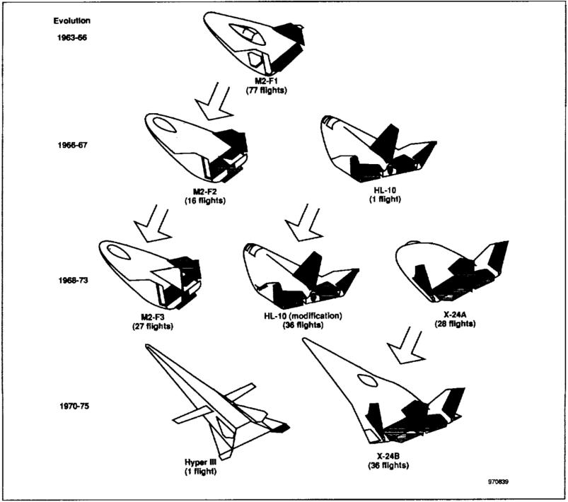
By viewing the historical evolution of blended bodies, an observer can see how certain design parameters evolve, such as slenderness. There is also the presence of control surfaces to maintain stability during subsonic and supersonic flight regimes to safely land as a conventional aircraft on a runway. This can be seen as a discontinuity in design philosophy: that is, capsules do not differ in shape gradually since they have reached aerodynamic characteristics to the point where they require parachutes to land safely. Similarly, lifting body aircraft such as the Hyper III require deployable wings for maintaining a high lift-to-drag ratio in the subsonic speed regime.
The changes between the X-24A and the X-24B can be seen in the drawings below. To save on costs, the frame of the X-24A was used and wrapped in the new “race-horse” shape. This shape allows for higher lift-to-drag ratios in the hypersonic speed regime [16].
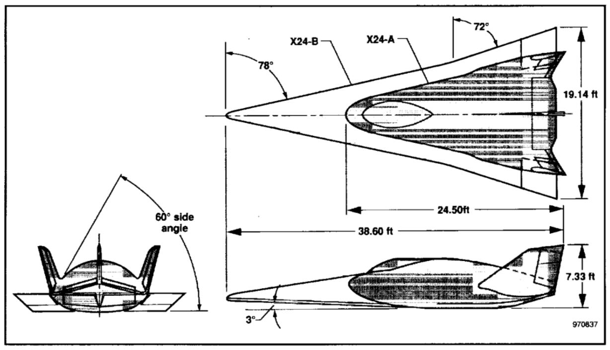
As thoroughly described in Chapter 1, the Model 176 is the focus of the senior project and the prime example of a blended lifting body.
2.2Background Material for Implemented Methods
2.2.1Vehicle Environment
When explaining the underlying physics behind this thesis, it is useful to first describe the properties of the environment in which the descent phase will take place and its initial assumptions. Returning from orbit requires the vehicle to begin at a state where it travelling very fast (orbital velocity) in a vacuum to approaching a runway near sea-level at subsonic velocity. The energy dissipation and accelerations required drive the design parameters for this stage.
The three initial environmental assumptions for trajectory analysis are as follows [3]:
- Planets are perfect spheres
- Atmosphere density varies exponentially with altitude
- Surface velocity due to planetary rotation is negligible compared to vehicle velocity
These are reasonable assumptions for the nearby rocky planets with atmospheres: Earth, Venus, and Mars. The atmospheres of these planets can be described by an exponentially thinning gas with increasing altitude held together by the planet’s gravity. Ideal gas relationships keep the gasses afloat, and the density function based on altitude can be described by a constant planetary value known as the atmospheric scale height:
The atmospheric scale height can describe the density at altitude by the equation [3]:
The value of is not the atmospheric density at sea level, but the logarithmic extrapolation from the atmospheric scale height to sea level. This density has a value of 1.3915 kg/m3, and the inverse of the atmospheric scale height is 7.165 km [3]. This scale height is considered to be valid for altitudes between 12 km and 100 km [2].
An important planetary value known as the gravitation constant defines the tangential velocity required to perfectly follow the curvature of a planetary body. This is dependent on the surface radius and surface gravity. The values for the gravitation constant of other bodies are shown in the table below:
| Planet | Radius [km] | Mass [] | Gravitational Constant [m3/s2] |
|---|---|---|---|
| Earth | 6371 | 1.00 | 3.981 e14 |
| Moon | 1737 | 0.0123 | 4.890 e12 |
| Mars | 3397 | 0.1080 | 4.290 e13 |
| Venus | 6052 | 0.8140 | 3.242 e14 |
| Jupiter | 71,492 | 318.40 | 1.265 e17 |
Returning from a low-Earth orbit is associated with returning from a certain speed and altitude. The altitude of return is defined at the Kármán line, or 100 km above sea level [17]. The orbital velocity will dependent on the angle of entry and apogee altitude, but is known to be equal to or greater than orbital velocity, which is calculated at the Kármán line as:
The factors used above will define the significant centrifugal contribution keeping the vehicle in steady flight.
2.2.2Vehicle Flight Path and Loads
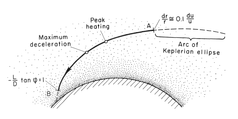
The region of interest in the atmosphere described in the previous section is a roughly 20 km band where the density increases by a factor of about 20 [3]. It is in this region where peak heating and acceleration is experienced by the vehicle. Chapman’s analytical method [3] for studying vehicle entry applies to these regions where the vehicle is kept flying due to a combination of orbital centrifugal forces and aerodynamic lift. When the flight path angle matches that which is predicted by conventional flat-earth subsonic flight (solely a function of lift-to-drag), the spacecraft is now low enough in the atmosphere to perform as an aircraft would and is outside the domain of the re-entry analysis. Likewise, outside of the atmosphere, the flight path angle can be predicted by orbital mechanics and is not relevant to the flight phase examined. Figure 2.7 shows the region analyzed as a solid line [3]:
In summary, the motion of the vehicle can be described by a dimensionless variable as a function of spacecraft velocity and constant parameters [3]:
For the purposes of design, it is important to note that the driving design parameters of this function are the drag coefficient and reference area. These will be tweaked according to how they affect this function of normalized velocity . The differential equation describing the vehicles path is explained below [3]:
The left side of the equation describes the vertical acceleration and the vertical drag force. The right side’s first term describes the difference between the gravity and centrifugal force, and the last term describes the lift force. In this location, the lift-to-drag ratio may be modulated to control the flight path. This equation is useful since it allows extrapolation of previous data on Earth to other atmospheres and mission profiles. The solutions for change based on the type of vehicle analyzed, since certain terms can be disregarded. The applied solutions are tabulated Table IV [3]:
| Solution | Vehicle | Dropped Term and Assumptions |
|---|---|---|
| Ballistic | Gravity, Centrifugal and Lift Forces | |
| Glide | Vertical Acceleration and Vertical Drag; | |
| Skip | Gravity and Centrifugal Forces; | |
| Satellite Decay | Small initial flight path angles |
With this general equation, some useful values may be found, such as tangential acceleration [3]:
While and are local values, for Earth they may be assumed to be the constant surface values. Additionally, while the flight path angle is small, the cosine denominator may be assumed to be unity. Applying earth values, the equation for the critical tangential acceleration is (in g’s):
This tangential acceleration value is critical for manned missions and must not be exceed more than 5 g’s for the human crew’s safety [2].
To plot the flight path on Earth, the descent angle and distance travelled can be computed:
It is important to keep in mind that this analysis requires to be nonzero and the flight path angle to be small, which is true for the critical regions of the descent stages of a spaceplane.
2.2.3Vehicle Design Parameters
The goal of this thesis is to optimize a design to save weight while meeting the mission requirements for a manned spaceplane. The descent flight phase is one of the largest contributors to the total weight of a spacecraft, since any thermal protection system or design features tailored for performance at this stage must be carried all the way to the end of the mission. The added weight for this phase is therefore significant since it detracts from the available payload to space for a given launch system. Additionally, to launch a given payload and the weight of the upper-stage vehicle, the launch system must be exponentially larger to meet a mission trajectory according to the rocket equation [2]:
One performance guideline for manned spacecraft is the deceleration limitation. This is dependent on the weight of the spacecraft, flight path angle, and drag properties. The equation for acceleration during descent, where is negative [2]:
For this reason, the vehicle weight required to support a given returning payload is a key parameter in determining the cost effectiveness of a descent vehicle. The structural weight is correlated to the volume of a capsule and planform area of a glider. The volume required can be determined by the following mission parameters [12]:
Spotted an error, or want to reply? Email me: leonardo.pinero42 [at] gmail [dot] com